Dosing Pot
Product Code: DP
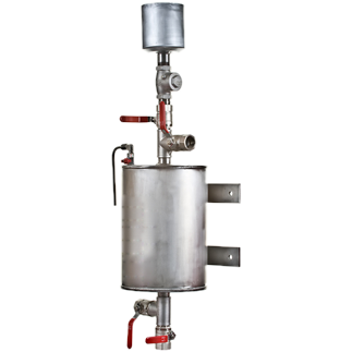
Dosing pots are required in order to feed liquid chemicals such as corrosion inhibitors into closed systems. The dosing pots consist of a stainless steel vessel with inlet (return) and outlet (flow) valves, a drain valve and a filling valve. A steel tundish, air release valve, wall mounting brackets and a non-return valve. Dosing pots can also be supplied without the valves, and air release valve if requested.
Product Type
Info Table
Additional Information
It is important that the dosing pots are fitted correctly in to the system to allow rapid chemical feed. This is best achieved by connecting across the main flow and return pipework. Ideally the flow connection should be made on the bottom of the dosing pot (Valve C), and the return the top (Valve B).
The dosing pot is designed for the conditions stated on the name plate, the system into which the dosing pot is installed should have adequate protection to ensure the dosing pot is operated within these limits at all times.
We are now manufacturing all our chemical dosing pots so they can be installed either left or right handed for ease of installation purposes. Floor stands are also available upon request.
- Size in Litres
- 3.5
- 5
- 6
- 10
- 11
- 13.5
- 15
- 16
- 18
- 20
- 25
- Product Code
- DP 3.5
- DP 5
- DP 6
- DP 10
- DP 11
- DP 13.5
- DP 15
- DP 16
- DP 18
- DP 20
- DP 25
- A
- 265
- 265
- 265
- 320
- 320
- 320
- 320
- 320
- 320
- 320
- 377
- B
- 275
- 355
- 395
- 395
- 395
- 395
- 490
- 570
- 570
- 685
- 685
- 585
- C
- 730
- 810
- 860
- 865
- 865
- 920
- 1022
- 1022
- 1142
- 1142
- 1040
- D
- 165
- 165
- 165
- 220
- 220
- 220
- 220
- 220
- 220
- 220
- 275
- E
- 76
- 100
- 155
- 155
- 155
- 227
- 295
- 295
- 430
- 430
- 233
- Max working pressure
- 14 bar
- 14 bar
- 14 bar
- 10 bar
- 10 bar
- 10 bar
- 10 bar
- 10 bar
- 10 bar
- 10 bar
- 8 bar
Operation
1. Isolate Pot: Closes valves
2. Drain Pot: Open valves A and D
3. Charge Pot: Close valve D and introduce solution via valve A
4. Expel Air: Open air vent until solution appears
5. Inject Treatment: Close valve A fully and open valves B and C
6. The dosing pot may reach temperatures up to 120°C. Protection or warnings should be applied to ensure that personnel do not come into contact with the pot so as to avoid burns
7. A check valve is to be installed to prevent accidental scolding and chemical saturation (blow back) of personnel operating the dosing pot
Maintenance
After long-term use the valves may require replacement. Periodic inspection should be conducted on the dosing pot in particular checking for corrosion wear. 1mm corrosion allowance is provided for in the design. If corrosion is found to be greater than 1mm the dosing pot should be taken out of use.
To calculate the size dosing pot you require, simply;
Divide the size of the total System Content (Boiler Rating (Kw) x 12 Litres per Kw) x 0.01 divde that figure by the amount of
dosing shots you intend to be adding to the system.
E.g 5000 Litre system (410 kw boilers x 12 Litres per Kw) x 0.01 ÷ 10 Shots = 5 Litre Dosing Po
+ -
Emflex
DOSING POTS
N.Minikin & Sons LimitedUnit 2B Brickyard Road, Roecliffe, York, YO51 9NS
Email: enquiries@minikins.co.uk Web: www.minikins.co.uk
Tel: 01423 326 789

01423 326 789
N.MINIKINS & SONS LIMITED
MINIKINS.CO.UK
Dosing PotProduct Code: DP
Dosing pots are required in order to feed liquid chemicals such as corrosion inhibitors into closed systems. The dosing pots consist of a stainless steel vessel with inlet (return) and outlet (flow) valves, a drain valve and a filling valve. A steel tundish, air release valve, wall mounting brackets and a non-return valve. Dosing pots can also be supplied without the valves, and air release valve if requested.
It is important that the dosing pots are fitted correctly in to the system to allow rapid chemical feed. This is best achieved by connecting across the main flow and return pipework. Ideally the flow connection should be made on the bottom of the dosing pot (Valve C), and the return the top (Valve B).
The dosing pot is designed for the conditions stated on the name plate, the system into which the dosing pot is installed should have adequate protection to ensure the dosing pot is operated within these limits at all times.
We are now manufacturing all our chemical dosing pots so they can be installed either left or right handed for ease of installation purposes. Floor stands are also available upon request.
- Size in Litres
- 3.5
- 5
- 6
- 10
- 11
- 13.5
- 15
- 16
- 18
- 20
- 25
- Product Code
- DP 3.5
- DP 5
- DP 6
- DP 10
- DP 11
- DP 13.5
- DP 15
- DP 16
- DP 18
- DP 20
- DP 25
- A
- 265
- 265
- 265
- 320
- 320
- 320
- 320
- 320
- 320
- 320
- 377
- B
- 275
- 355
- 395
- 395
- 395
- 395
- 490
- 570
- 570
- 685
- 685
- 585
- C
- 730
- 810
- 860
- 865
- 865
- 920
- 1022
- 1022
- 1142
- 1142
- 1040
- D
- 165
- 165
- 165
- 220
- 220
- 220
- 220
- 220
- 220
- 220
- 275
- E
- 76
- 100
- 155
- 155
- 155
- 227
- 295
- 295
- 430
- 430
- 233
- Max working pressure
- 14 bar
- 14 bar
- 14 bar
- 10 bar
- 10 bar
- 10 bar
- 10 bar
- 10 bar
- 10 bar
- 10 bar
- 8 bar
Operation
1. Isolate Pot: Closes valves
2. Drain Pot: Open valves A and D
3. Charge Pot: Close valve D and introduce solution via valve A
4. Expel Air: Open air vent until solution appears
5. Inject Treatment: Close valve A fully and open valves B and C
6. The dosing pot may reach temperatures up to 120°C. Protection or warnings should be applied to ensure that personnel do not come into contact with the pot so as to avoid burns
7. A check valve is to be installed to prevent accidental scolding and chemical saturation (blow back) of personnel operating the dosing pot
Maintenance
After long-term use the valves may require replacement. Periodic inspection should be conducted on the dosing pot in particular checking for corrosion wear. 1mm corrosion allowance is provided for in the design. If corrosion is found to be greater than 1mm the dosing pot should be taken out of use.
To calculate the size dosing pot you require, simply;
Divide the size of the total System Content (Boiler Rating (Kw) x 12 Litres per Kw) x 0.01 divde that figure by the amount of
dosing shots you intend to be adding to the system.
E.g 5000 Litre system (410 kw boilers x 12 Litres per Kw) x 0.01 ÷ 10 Shots = 5 Litre Dosing Po
01423 326 789
N.MINIKINS & SONS LIMITED
MINIKINS.CO.UK